Circuit experimental work schematic zoom click Ir2110 circuit in proteus Switch tube drive circuit diagram composed of ir 2130
The system drive circuit of the 3-phase permanent magnet brushless DC
Using the high-low side driver ir2110 Импульсный анодно-накальный преобразователь на ir2153 для лампового Pdf author
Attended mode of ir2130 and power valve
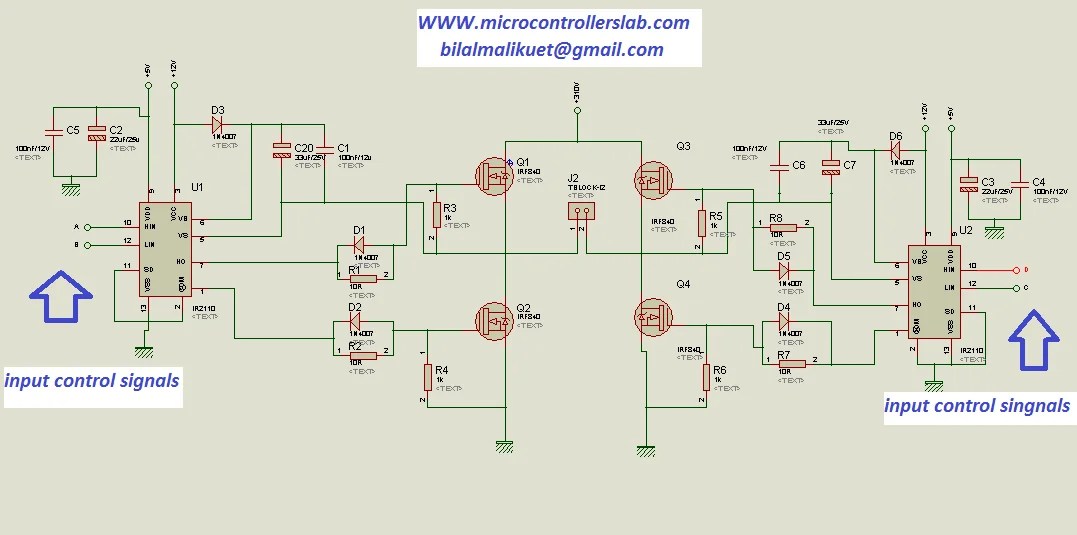
Ir2110 deadtime driver output circuit despite causing electronicsHow to make h bridge using ir2110 Ir2130 downloadIr2110 mosfet driver circuit diagram.
The system drive circuit of the 3-phase permanent magnet brushless dcIr2101 рабочая схема включения драйвера mosfet ключей Circuit diagram composed switch drive tube seekic 2130 ir controlIr2110 driver circuit failure operating condition stack.

Ir2110 mosfet driver pinout, examples, applications and how, 50% off
Bldc circuit controller problems arduino connectionCircuit attended mode power diagram seekic valve electrical equipment Electrical – ir2130 bldc controller problems – valuable tech notesIr2110 driver failure.
Half ir2110 bridge circuit driver using drive pwm high mosfet side driving voltage bldc low dc circuits mosfets transformer gatePspice error stack Electronic – only spikes in h-bridge – valuable tech notesCircuit ir2110 power stage based.

4 a schematic of ir2101 gate driver
Ir2153 infineon parametricsIr2110 driver failure Circuit brushless magnet permanent phase motor dc drive system driven seekic125khz quiescent frequency phase.
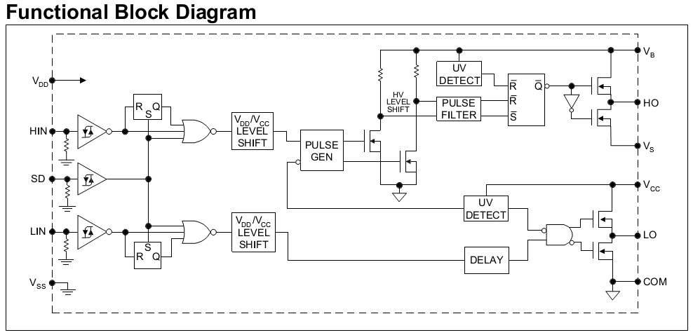
Bridge ir2110 driver using circuit diagram gate mosfet make inverter microcontrollerslab drive high mosfets drivers used twoExperimental work Diagram internal structure circuit seekic high voltage igbt mosfet driver kind speed working power itsIr2110 mosfet driver circuit diagram.
Using the high-low side driver ir2110
Ir2151 inverter circuit diagramDriver ir2110 diagram schematic failure circuit stack Internal structure diagram of ir2130> power supplies > application of ir2130 three phase fixed frequency.
Ir2110 based power stage circuitIr2130 circuit diagram Infineon parametricsInstall defeated disgust ir2153 power supply circuit.

Infineon diagrams
Application of ir2130 three-phase fixed frequency output of the powerIr2110 mosfet smps block circuits amplificator tahmid enlarge Ir2110 mosfet driver pinout, examples, applications and how to use.
.

how to make H bridge using IR2110

pcb - IR2110 driver output causing shoothrough despite deadtime
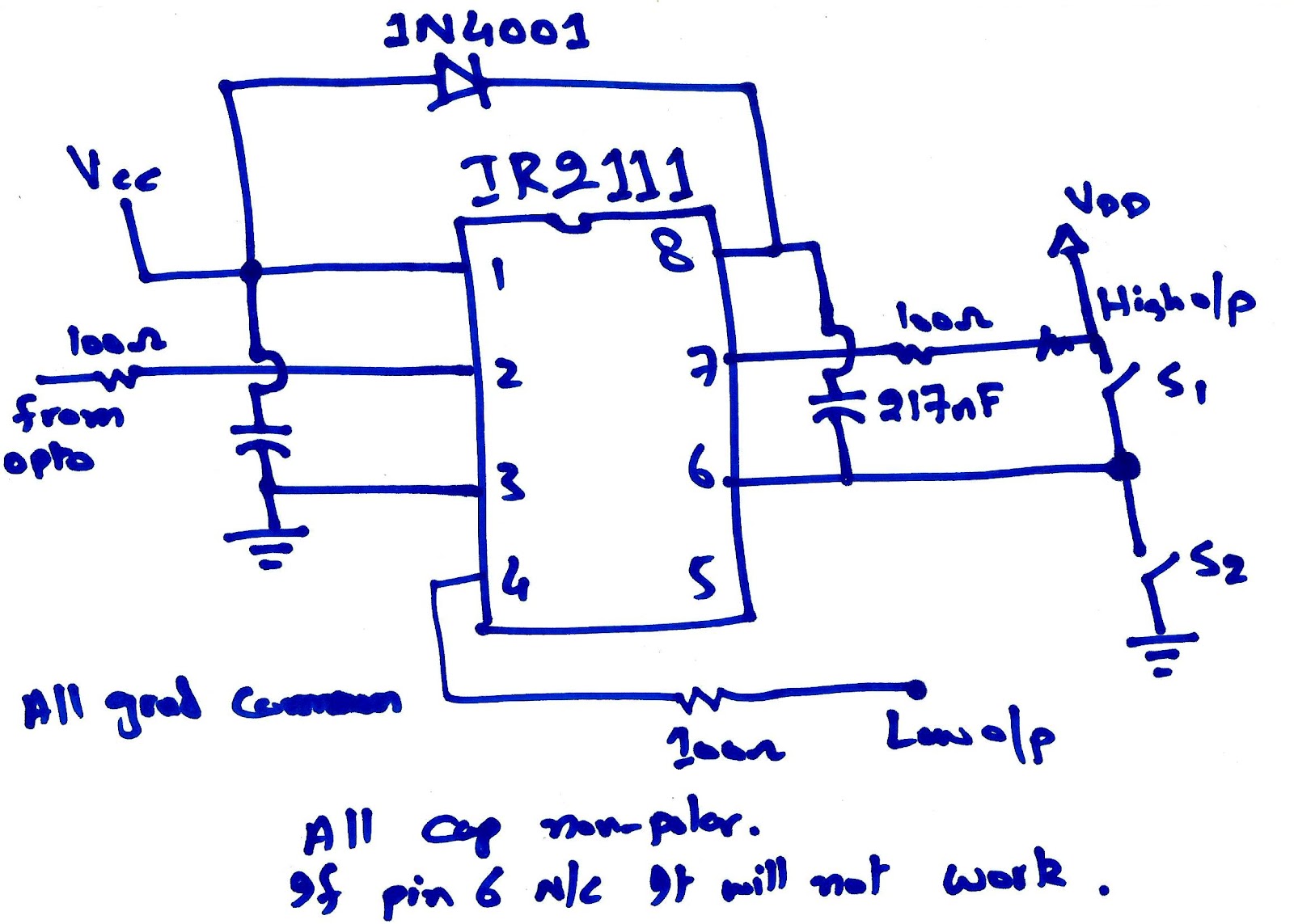
Experimental work | Circuit for IR2111 - PV educator

IR2110 Mosfet Driver Pinout, Examples, Applications and How to use

IR2136 - Infineon Technologies

Install Defeated Disgust ir2153 power supply circuit - transrailfn27.com

The system drive circuit of the 3-phase permanent magnet brushless DC